On this page you can learn more about:
- Inertial Laboratory
- IMU Laboratory Calibration
- „Fly-in-the-Laboratory” Navigation System Test Environment
Inertial Laboratory
Testing and calibration of inertial sensors in general require a precisely known motion simulator. Higher value inertial sensors are in the manufacturing process typically calibrated and acceptance tested on either single sensor or sensor triad level. After the inertial measurement unit, in general comprised of an accelerometer triad and a gyro triad, was finally integrated, the IMU is again calibrated and acceptance tested.
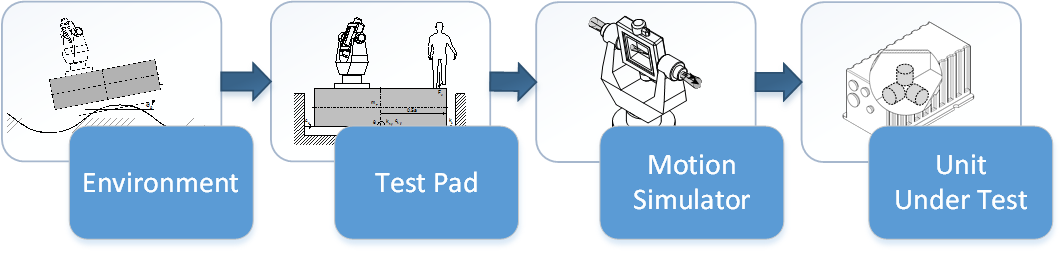
The test principle aims to subtract from accelerometer measurements both local gravity vector and applied linear reference motion acceleration, and identify the sensor specific body-fixed and signal-proportional error parts inspite the existence of sensor noise. In the case of gyro measurements both Earth’s rotation rate and applied angular reference motion rate are compensated for gyro error identification. The total manufacturing process is usually designed to achieve high yields. The better the design of the sensors the less calibration compensation is needed over the temperature and measurement range.
Sensor aging requires monitoring of its performance and sometimes also recalibration. Testing and calibration of inertial sensors in an inertial laboratory is vulnerable to both environmental disturbances and motion reference errors. Hence the motion simulator is typically mounted on the properly dimensioned floating basement, which aims to decouple setup from the environment as good as possible.
When the basement is not conservatively dimensioned, the motion simulator may in operation excite the basement. The total inertial laboratory setup errors, including e.g. environmental disturbances, base plate misalignments, gravity deflections of the vertical or anomaly, motion simulator or unit under test mounting imperfections, shall be negligible compared to the errors of the unit under test to be estimated. Necessary inertial laboratory instruments may include single- or multi-axis rate-tables, climate chambers, shakers and shock exciters.
Literature
- Seminar “Navigation and Data Fusion”.
- A. Lawrence, Modern inertial technology: Navigation, guidance, and control, 2nd ed. New York, NY: Springer, 2001.
- IEEE Recommended Practice for Inertial Sensor Test Equipment, Instrumentation, Data Acquisition, and Analysis, IEEE Std. 1554-2005.
- C. Blum, B. Braun, J. Dambeck, and M. Kägi, “Inertial Laboratory Simulation,” in DGON Inertial Sensors and Systems (ISS) Symposium Gyro Technology. Karlsruhe, 2014.
IMU Laboratory Calibration
Inertial sensor laboratory calibration is based on identification and subsequent compensation of the sensor’s errors. Typical sensor errors to be calibrated are axis-misalignments, scale-factors, biases and nonlinearities. Although, noise cannot be compensated due to its stochastic nature, it still needs to be characterized to evaluate a sensors’ performance.

To determine scale factors and nonlinearities, the sensor needs in general to be stimulated with reference signals over its complete input range. This requires the use of centrifuges for accelerometers and turntables for gyroscope calibration. The calibration of axis-misalignments however, can be performed using reference inputs only. Typically, six symmetric poses relative to the reference signal are used to determine the axis-misalignments for a sensor-triad. To minimize the influence of stochastic errors, the output signals are averaged for each pose. If stochastic errors or a limited resolution do not allow the use of the Earth’s rotation as a reference signal, the use of rate tables is mandatory.
A sensor bias is defined as the sensor’s output, in the case that there is no input signal. To determine the bias, the sensors are oriented perpendicular to any natural input, like gravity or the Earth’s rotation. The remaining output is then averaged over a certain time to minimize the effects of stochastic errors. As most sensor errors are influenced by the environment, these errors have to be characterized for a wide range of temperatures and temperature changes. In spite standard test procedures for a wide range of different sensors are defined by the IEEE, many different calibration procedures exist. These are usually tailored to specific sensor characteristics, desired application and available testing equipment.
Literature
- IEEE Aerospace Electronics Systems Society. IEEE recommended practice for inertial sensor test equipment, instrumentation, data acquisition, and analysis. New York, N.Y: Institute of Electrical and Electronics Engineers, 2005, Nr. 1554.
- IEEE Aerospace Electronics Systems Society. IEEE standard specification format guide and test procedure for single-axis interferometric fiber optic gyros. New York, N.Y., USA: Institute of Electrical and Electronics Engineers, 2008, Nr. 952.
- IEEE Aerospace Electronics Systems Society. IEEE standard specification format guide and test procedure for single-axis laser gyros. New York, N.Y., USA: Institute of Electrical and Electronics Engineers, 2008, Nr. 647.
- IEEE Aerospace Electronics Systems Society. IEEE standard specification format guide and test procedure for Coriolis vibratory gyros. New York, N.Y: Institute of Electrical and Electronics Engineers, 2004, Nr. 1431.
- IEEE Aerospace Electronics Systems Society. IEEE standard specification format guide and test procedure for linear, single-axis, nongyroscopic accelerometers. New York: Institute of Electrical and Electronics Engineers, 2008, Nr. 1293.
- Lawrence, Anthony. Modern inertial technology: Navigation, guidance, and control. 2. ed., corr. 3 print. Mechanical engineering series. New York, NY: Springer, 2001.
„Fly-in-the-Laboratory” Navigation System Test Environment
Testing, verification and validation of integrated navigation systems is essential for certification. Hardware-In-the-Loop (HIL) tests are performed in real-time. Black-box testing strategies require sufficient combinations of all important system stimuli. Since the degrees of freedom of an integrated navigation systems is quite high, the necessary test effort can easily be underestimated. Since flight testing is much too expensive, it is of utmost importance to perform a high percentage of system testing in the laboratory.

Since product updates or upgrades require sufficient test coverage, verification and validation have in general repeatedly to be performed. Thus an optimized test plan in order to keep the number of test hours as low as possible, but nevertheless provide full test coverage, is a competitive advantage. Since the linear acceleration of a flight trajectory cannot be stimulated in a laboratory environment, the inertial sensor measurements are commonly provided via an external interface when the system is resting.
The simulation of flight trajectories in inertial quality. i.e. together with perfect IMU measurements, is therefore essential. For the simulation of GNSS antenna signal a space segment simulator is required.
When the integrated navigation system contains more than just an IMU and a GNSS receiver, the other navigation sensors and subsystems need to be either as well be stimulated in a coordinated manner. This can e.g. cover magnetic field, air data or a visual environmental projection. In case a multi-sensor integrated navigation system cannot be fed properly with a “fly-in-the-lab” environment, the implementation of appropriate test modes may be useful.
Literature
- NATO Standardization Office. A Standardised Open System Architecture Interface To Enable Simulator Testing Of Integrated GPS/Inertial Navigation (IN) Equipment, STANAG 4572.
- L. Goercke, F. Holzapfel, and J. Dambeck, “Aerodynamic Flight Simulation in Inertial Quality,” in Proceedings of the 2013 International Technical Meeting of The Institute of Navigation, 2013, pp. 415–425.
| ⇦ Navigation Systems | return to overview | Modeling and Simulation ⇨ |